Perceptuum 3 Renderer Architecture Description
Summary
This article is an augmented architecture description for the Perceptuum 3 renderer. It contains outlines of the ethos and techniques, and simplified views of all the models of the system (as for the Unified Software Development Process). (3000 words)
- subject
- renderer, architecture, documentation
- uri
- http://www.hxa.name/articles/content/p3-architecture-description_hxa7241_2004.html
- license
- Creative Commons BY-SA 3.0 License.
Contents
Introduction
Architecture Description
For the Unified Software Development Process[1.1], an ‘architecture description’ is a view of the whole system structure with the important characteristics made more visible by leaving details aside. It is composed of views of each and all the models of the system, based on architecturally significant use cases (most important functionality and risk). Production of this document marks the end of the elaboration phase of this project.
Proposition
The currently dominant approach to global illumination architecture is based on the monte-carlo ray-tracing method. Although it has strengths in generality and theoretical physical fidelity, its weaknesses show in practical use. The stochastic essence translates to an obdurate noisiness, and the high dimensionality of the domain causes insurmountably long convergence. The incoherency is not supported by common specialised hardware.
The requirements of users are principally aesthetics and speed, and these may be better served by a different architecture with a different emphasis. The initial ethos directing the design is:
- Target aesthetic realism instead of physical realism
- Exploit graphics card capability
That is: deliberately try to simulate less completely, and orient towards the strongest computing resource. From these follow some primary internal aims:
- Prioritise speed/robustness/usability over accuracy
- Emphasise specialised features rather than general techniques
- Focus on OpenGL[2.4]
And these can be more broadly guided by an external product aim:
- Be a technology able to adapt and integrate into other rendering systems
Algorithm
The core algorithm can be characterised by the term: projection-interpolation light gathering.
An elucidation of which is: inward light at any point is determined by projection — passing scene objects through a transform and rasterization pipeline. And, most points do not have inward light determined, but instead have it approximated by interpolating points that are fully determined. The overall direction of the algorithm is to start at the eye and move out, gathering light, rather than start at light sources, spreading light. To summarise:
- do illumination by interpolation of inward light
- do inward light integration by projection
- do projection with OpenGL
This is a re-use and adaptation of the algorithm devised by Ward[2.2] and used in the ‘Radiance’ renderer. The modifications are to avoid ray tracing mostly, and avoid monte-carlo completely — replacing them with projection, and to augment it with separate feature sub-algorithms for caustics, volume scattering, motion-blur, etc.
If the number of gatherings is of the order of 1000, and each has a resolution of about 1000 points, and projecting a much simplified geometry: that would approximate the effort needed for a projective rendering of a single whole-screen image. Such a rendering can be done in the order of a few seconds.
Benefits
Projection is faster and more robust than monte-carlo ray tracing. It exploits coherence, and uses more fully the available scene data. Where monte-carlo requires practically infinite time to find small features, projection can easily capture them in an accumulation buffer.
Projection can be directly accelerated with specialised graphics hardware, and maybe even mostly removed by running in parallel to the CPU.
Separating feature techniques allows more specialised, faster and more robust, approximations, whereas a generalised monte-carlo approach becomes intractable with multiple dimensions.
Avoiding monte-carlo removes otherwise ineradicable noisiness in images. Aliasing can be suppressed by control of scene level-of-detail, and other established projection techniques.
Eliminating monte-carlo allows simplification of BRDF/shader handling since probability distributions are not needed.
Global light gathering more simply and automatically calculates relevant illumination, where general photon mapping (global light spreading) needs special restriction of its domain to what is visible to the viewer.
Details
Rasterization
The first operation is projection of the scene as a triangle mesh, into pixels containing the IDs of the visible triangles. Every pixel can then be visited to intersect a ray from the camera, using the ID and perhaps other geometric data. Maybe a triangle list can be extracted from the pixels, then each rasterized more incrementally.
The surface point determined for each pixel is then used. The position is sent to the illumination package to get all the incident light. The emission is read directly. Both can then be put through the (light-)interaction package to calculate the outward light towards the eye.
Illumination
First Level
The global gather algorithm is separated into two parts, the first level, nearest the eye, is made more sophisticated. The incoming light determination is separated into four parts: gather, ray trace, photon map, translucency map. They will be combined by simple addition, which means their light paths must not overlap.
The gather is itself separated into two parts: indirect and direct. The direct part only gathers emissive surfaces, and at just below screen resolution, so that shadows will be sharp. The indirect part gathers a shadowed render using nominated and brightest emitters, which provides an extra level of light bounce.
Deeper Levels
These less important contributions can be evaluated very much as the original Ward global gather. The trees can start at low resolution on the image, and, with high error allowance, propagate by ray tracing. The gather projection at each node could be with shadows, or just emitters only, — the tradeoff needs to be experimented with. Either way the accumulation can probably be simplified to pure diffuse.
General
All light gatherings are stored. A straightforward explicit representation would require a lot of, but not too much, memory. Reducing size would be beneficial to performance so some simple compression may be good. Conversion to spherical wavelets seems more appropriate than spherical harmonics, since the data would be closer to piece-wise linear.
The gather could be a uniform hemi-(or whole)-cube. More efficient may be a single surface-parallel plane, since for diffuse reflection low-angle light is a small contributor. Perhaps best would be to orient and concentrate a single plane perpendicular to the BIDF ‘peak’ (if some analysis can be done), supplemented with a surface-parallel plane. A basic requirement is that the resolution be greater than the nyquist limit for the BIDF (discluding perfect specular).
Density of gathering points is set by the Ward error term. Interpolation between points is done with Ward gradients[2.3].
OpenGL Component
Since projection is used ‘internally’ rather than for the final image, various approximations can be made. Models can have: lower level of detail, no textures, simple shaders. Specular reflection is approximated with glossy, glossy transmission is approximated with specular. No ray tracing or photon mapping or translucency mapping is used.
So that light paths can be separated for different calculation, projection must parameterise: shadowed renders, transparency (per item), primary/secondary emitters (per item). Also projection needs to able to just produce triangle IDs.
Antialiasing and fog can be done straightforwardly. Transparency and shadows require a bit more work.
The restriction of OpenGL 1.1 to 8 bits per color channel means special work will be needed to handle bright emitters like the sun and sky. A higher level scene-graph component wrapper will be needed to maintain performance for large scenes.
Other Transport
At the top level extra features are enabled: ray tracing is used to follow perfect specular interaction only, and propagates in a tree for both reflection and transmission. Photon mapping is used only for nominated objects, and built by gathering at points on the object surface, and traced with perfect specular only. Translucency mapping is used only for nominated objects.
Interaction
The BIDF class is fully general, and mostly follows its mathematical form: returning a scaling (for each spectral channel) given an inward and outward direction. But it must separate perfect specular interaction: by returning a scaling (of a perfect inward ray) for an outward direction. The BIDF must also provide a rough approximation of itself in traditional form: diffuse and specular weightings and shininess value.
Some built-in BIDFs are provided: perfect diffuse, fresnel specular, Ward (and probably others). But plugins are enabled, specified in the model file with lists of tagged parameters/textures.
Sampling
Depth Of Field
Can be done with the image convolution technique, probably with a limit on lens size to constrain the filter size. The weakness is with reflections, which would be blurred according to the focus of the reflecting surface, rather than the reflected objects themselves. But only when the reflective surface is in focus would the fault be noticeable.
Motion Blur
The moving objects case can be handled by separating rendering into two passes, and treating indirect and direct illumination differently. The first pass renders all static objects with indirect gather, static photon map and translucency map illumination. All indirect gather is done with the scene fixed in mid-time position. The second pass renders iteratively: each step accumulates direct gather and ray tracing illumination, and accumulates renders of moving objects, each on a separate sub-image. When iterations complete, everything is merged and composited.
The moving camera case can be handled by including motion vectors with the pixels, then filtering the normally rendered image.
To combine depth of field and both kinds of motion blur, follow the moving objects process and apply depth of field to each sub-image, then apply the moving camera vector-filtering at the end.
Adaptive Supersampling
This image refinement can be done post-render, by conventional distribution ray tracing techniques. High contrast pixels can be fully sampled in both dimensions of time and lens position.
Modelling
The scene is a tree of two principal node types: objects and instances, both inheriting a common interface. An object contains a shape definition, but no transform. An instance references objects or instances, each with a transform. The basic object/instance common interface defines both projectable and ray traceable capabilities. An object need not be a triangle mesh internally, but must be able to generate one, preferably at different levels of detail.
Every triangle is uniquely identifiable. All scene tree nodes note how many triangles they contain: leaf objects know their triangle counts, instances sum their sub-part counts. So navigating a path from the root can either determine or find a particular numbered triangle. Numberings can be stored in separate trees for different levels of detail.
To spatially index the scene, each instance has an octree holding the triangles of sub-objects and the bounds of sub-instances.
Imaging
The basic format is the OpenEXR high dynamic range image. A tonemapping, gamma and color transform can be used to produce RGB images in PNG format. Supplementary buffers containing z or other geometry, and alpha can be included.
Parallelizing
Fully exploiting the GPU and multiple CPUs is not straightforward. Having the GPU work in parallel to the CPU is awkward because the GPU is used in the middle of a pipeline, and substantial computation is dependent on data produced. Having multiple CPUs work in parallel is awkward because substantial computation is routed through a single GPU.
The GPU can be wrapped by a thread running a queue. Then multiple CPU threads can submit requests and lookup results, without blocking their execution too much.
Illumination pipelines (incorporating GPU work) can be split into two: a ‘seed’ pipeline to do all computation leading to submitting GPU requests, and a ‘harvest’ pipeline to do all computation on GPU results. Since multiple pipeline instances would be required across the rasterization, both CPU and GPU parallelization is possible, as long as each individual pipeline completes its seed before starting its harvest. However, experimentation with prototypes is needed to see if this refactoring is really worth it.
Requirements Model
A system's external behaviour is described by a set of use cases. Each use case is a sequence of actions that provide the user with a result of value. With some supplementary requirements, this constitutes the requirements model.
The external behaviour has a very simple structure, the complexity being contained in the algorithms.
Use Cases
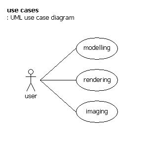
Modelling
actor – user
- input external scene file of some common format, maybe also a command file
- take output P3 command file
Rendering
actor – user
- input command file
- execute renderer
- (maybe read output error file, then repeat from first step)
- take output HDR image file
features:
- quick projective render
- text scene file, maybe xml, maybe X3D
- image output in HDR, with alpha, z
- selectable rendering features, quick mode
- simple general triangle mesh models
- hierarchical object models
- level of detail model support
- global illumination
- generalised shaders
- sub-surface-scattering / translucency
- image texturing
- sky illumination
- depth of field
- caustics
- motion blur
- generalised emitters
- polymorphic plugin shaders
- simple fogging
- bump mapping
- displacement mapping ?
Imaging
actor – user
- input command file
- input HDR image file
- execute image converter
- (maybe read output error file, then repeat from first step)
- take output RGB image file
features:
- tonemap
- RGB, real-Ward output color format
- PNG image format
- glare
Supplementary Requirements
Use of OpenGL 1.1, and maybe higher level scene-graph library.
Reuse of components and libraries: Perceptuum2, Radiance, X3D, OpenEXR, libpng, boost, stlport, cppunit.
Portability to different compiler/OS/hardware.
Analysis Model
This has the purpose of refining the use cases in more detail, and making an initial allocation of the behavior of the system to a set of objects. The perspective is from the outside, leaving implementational considerations aside.
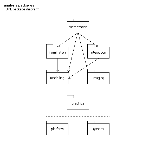
Packages
The broad structure is an ‘open’ hierarchy: higher packages use/depend on any lower ones. There are three divisions: project specific, general graphics, and non-application specific general.
- rasterization
- illumination
- interaction (light interaction)
- modelling
- imaging
- graphics
- platform
- general
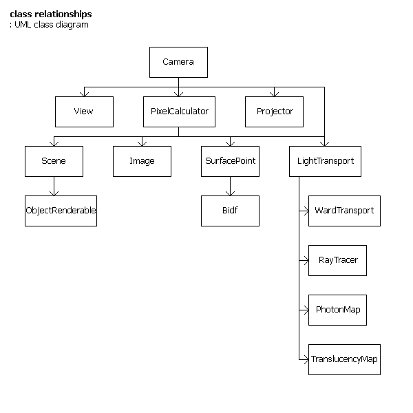
Classes
Some key classes can be found and their basic relationships sketched.
classes listed in package groups
rasterization
- Camera
- View
- PixelCalculator
illumination
- Projector
- LightTransport
- WardTransport
- RayTracer
- PhotonMap
- TranslucencyMap
interaction
- SurfacePoint
- Bidf
modelling
- Scene
- ObjectRenderable
imaging
- ImageHdr<>
Design Model
This defines the static structure of the system as subsystems, classes, and interfaces; and realizes the use-cases as collaborations among those elements.
Classes
Further classes are added to the packages.
classes listed in package groups, with architecturally significant members in bold
rasterization
- Camera
- View
- PixelCalculator
illumination
- Projector
- OpenGL
- Gathering
- GatheringInterpolation
- LightTransport
- WardTransport
- RayTracer
- Ray
- PhotonMap
- TranslucencyMap
interaction
- SurfacePoint
- Bidf / Brtdf
- Brdf
- Btdf
- Bssrdf
- Light
modelling
- Scene
- Bound
- Material
- TriangleImplicit
- TriangleExplicit
- Vertex
- Mesh
- ObjectRenderable
- ObjectInstance
- ObjectInstanceMoving
- ObjectMesh
imaging
- ImageHdr<>
- GammaTransform
- ColorTransform
- ToneMap
- PngWriter
- Compositor
graphics
- Octree<>
- Vectors
- Matrixes
- Quaternion
- CieXyz
- Rgb
- XyzE
- Polar
- Filters
platform
- windows
- WinThread
- WinThreadLock
- linux
- mac
general
- Exceptions
- Thread
- ThreadLock
- Logger
- Float01
- hxa7241vector
- VectorEx
- Sheet
- TimePoint
Class Interfaces
The interfaces are divided into methods, each with informal parameter lists.
interfaces of important classes
Camera
- render
- [in]scene,
- [in]view,
- [out]imageBuffers
PixelCalculator
- construct
- [in]scene
- getPixel
- [in]objectid,
- [in]pixel/point position,
- [out]light
Projector
- construct
- [in]params
- project
- [in]scene,
- [in]view,
- [out]imageBuffers
LightTransport
- getIllumination
- [in]scene,
- [in]geometry,
- [in]outDirection,
- [in]isFullSphere,
- [out array]lights,
- [out]light,
- [out array]LightStreams
WardTransport
- getIllumination
- [in]scene,
- [in]normal,
- [in]isFullSphere,
- [out array]lights
RayTracer
- construct
- [in]WardTransport
- getIllumination
- [in]scene,
- [in]geometry,
- [in]outDirection,
- [out]light
PhotonMap
- getIllumination
- [in]position,
- [out array]LightStreams
TranslucencyMap
- getIllumination
- [in]position,
- [out]
SurfacePoint
- getEmission
- [out array]lights
- isTransmissive
- [out]bool
- getScalingGeneral
- [in]inVector,
- [in]outVector,
- [in]arraysLength,
- [in array]scalingWavelengths,
- [out array]scalings
- getScalingSpecular
- [in]outVector,
- [out]scalingSpecularReflect,
- [out]scalingSpecularTransmit
- getApproximation
- [out]diffuse,
- [out]specular,
- [out]shininess
Bidf
- isTransmissive
- [out]bool
- getScalingGeneral
- [in]inVector,
- [in]outVector,
- [in]arraysLength,
- [in array]scalingWavelengths,
- [out array]scalings
- getScalingSpecular
- [in]outVector,
- [out]scalingSpecularReflect,
- [out]scalingSpecularTransmit
- getApproximation
- [out]diffuse,
- [out]specular,
- [out]shininess
Scene
- setTime
- [in]timepoint
- enumerate
- [in]pixelsize,
- [in]viewpoint
- getBound
- [out]bound
- getIntersection
- [in]ObjectRenderableId,
- [in]Ray,
- [out]isHit,
- [out]distance,
- [out]Intersection
- visitObjects
- [in out]visitorObjects
ObjectRenderable
- setTime
- [in]timepoint
- enumerate
- [in]pixelsize,
- [in]viewpoint
- getBound
- [out]bound
- getIntersection
- [in]ObjectRenderableId,
- [in]Ray,
- [out]isHit,
- [out]distance,
- [out]Intersection
- visitObjects
- [in out]visitorObjects
ImageHdr
- setPixel
- [in]light
Interactions
The main render use case can be realized as a high level pseudo-code sequence, each line being an operation description or method call.
Main Sequence
Camera::render
   pre render
      build photon map
      build translucency map
      enumerate scene [using view]
   main render
      Projector::construct for id production
      Projector::project
      start illumination cache
         loop thru pixels following low res grids
            at each point and ray trace node
               call LightTransport to make illumination
      loop thru pixels
         PixelCalculator::getPixel
            get SurfacePoint from Scene
            Bidf::isTransmissive
            LightTransport::getIllumination
               WardTransport::getIllumination
               if Bidf::getScalingSpecular larger than zero
                  RayTracer::getIllumination
               PhotonMap::getIllumination
               TranslucencyMap::getIllumination
            SurfacePoint::getEmission
            calculate overall light interaction equation
               Bidf::getScalingGeneral
               Bidf::getScalingSpecular
         Image::setPixel
      apply depth of field
   post render
      adaptive supersample
         pick high-contrast pixels
            loop thru timesteps
               loop thru lens points
                  trace into pixels
Moving Objects Sequence
set time point to mid
render static objects
step through time
   render top layer
      background accumulation, and each moving object on a separate sub image
      accumulation
Moving Camera Sequence
render, including pixel vectors
convolve image according to vectors
Deployment Model
Rather than distribute across computational nodes, this divides the system into separate executable programs of particular types.
Command-line programs:
- modeller - in: (external scene file, command file) out: (P3 scene file)
- renderer - in: (commands (options, scene)) out: (log, HDR standard image)
- imager - in: (commands, HDR standard image) out: (log, RGB PNG)
- executor - batch them together
Optional dynamic-link plugins can be added:
- Bidf
- ObjectRenderable
Implementation Model
This contains general implementation notes and guides.
Component/libraries reused:
- OpenGL
- OpenSceneGraph
- Perceptuum2
- Radiance
- X3D
- OpenEXR
- libpng
- boost.org
- stlport.org
- cppunit
Code details:
- headers have .hpp filename extension
- body code has .cpp filename extension
- non-nested namespaces
- avoid templates except basic usage
- warn if any data requirement is defaulted
- make a nested exception class to capture message stack
- integrated unit tests
Test Model
Though testing is usually not part of the architecture for USDP, an integrated XP[1.3] approach to testing makes it so.
The overall strategy is that testing will be mostly unit testing — the complex, numerical nature of the algorithms demand detailed probing in several places. System testing will be by viewing specially constructed test scenes.
Plan
Construction order:
- Basic skeleton version of apps
- Basic visualising window app
- OpenGL component prototype
- Basic versions of some packages
- Illumination and projective rendering
- Gathering and interpolation
- Rasterization
- Modelling
- Imaging
- Interaction
- Ray tracing
- Rasterization refinements
- Depth of field
- Motion blur
- Adaptive supersampling
- Caustics
- Caustic rendering
- Illumination refinement
- Translucency
- Translucency rendering
- Illumination refinement
- BSSRDF
- BIDF
- Plugins
- Imaging refinement
- Better tonemap
- HDR format
- Glare
- Multi CPU support, and GPU parallelization
References
Software Engineering
- [01.01] Booch, Jacobson, Rumbaugh; ‘The Unified Software Development Process’, Addison Wesley, 1999.
- [01.02] Fowler; ‘UML Distilled’ 3rd ed, Addison Wesley, 2003.
- [01.03] Beck; ‘Extreme Programming Explained’, Addison Wesley, 1999.
Basic Approach
- [02.01] Tabellion, Lamorlette; ‘An Approximate Global Illumination System for Computer Generated Films’, Siggraph Proceedings, 2004.
- [02.02] Ward, Rubinstein, Clear; ‘A Ray Tracing Solution for Diffuse Interreflection’, Siggraph Proceedings, 1988.
- [02.03] Ward, Heckbert; ‘Irradiance Gradients’, Siggraph Proceedings, 1992.
- [02.04] Neider, Davis; ‘OpenGL Progamming Guide’ (red book) 2nd ed, Addison Wesley, 1997.
- [02.05] Nijasure, Pattanaik; ‘Real-Time Global Illumination on GPU’, unpublished, 2004.
- [02.06] Krivanek, Gautron, Pattanaik, Bouatouch; ‘Radiance Caching for Efficient Global Illumination Computation’, IEEE transactions on visualisation and computer graphics, 2004.
Feature Techniques
- [03.01] Glassner; ‘Introduction To Ray Tracing’, Academic Press, 1989.
- [03.02] Wann Jensen, Buhler; ‘A Rapid Hierarchical Rendering Technique for Translucent Materials’, Siggraph Proceedings, 2004.
- [03.03] Wann Jensen; ‘Realistic Image Synthesis Using Photon Mapping’, AK Peters, 2001.
- [03.04] Ward, Rushmeier, Piatko; ‘A Visibility Matching Tone Reproduction Operator for High Dynamic Range Scenes’, ?, 1997.
- [03.05] Mulder; ‘Fast Perception-Based Depth of Field Rendering’, ?, 2000.
- [03.06] Ward, Eydelberg-Vileshin; ‘Picture Perfect RGB Rendering Using Spectral Prefiltering and Sharp Color Primaries’, Eurographics workshop on rendering, 2002.